
The component box can later be modified and adapted to new conditions.
Connections
If you need additional connection pins, click with the right mouse button on the component box and select the option Pins in the context menu. Here you select Place and position the pins on the casing. This is also where you can modify the existing connection pins.
Copying, Deleting, etc.
With the parameter menu option Change size, you can correct the size of the box by selecting the frame of the casing. Symbols (symbol type) which are thereby included in or excluded from the casing are managed automatically or not depending on the Parameters.
With the parameter menu options Drag, Move, Delete, Copy, you can immediately influence the casing in the given manner, always without the content, but with the connection pins.
With the context menu option component box, you can subsequently work on the component box with Remove, Move, Drag and Copy with included symbols.
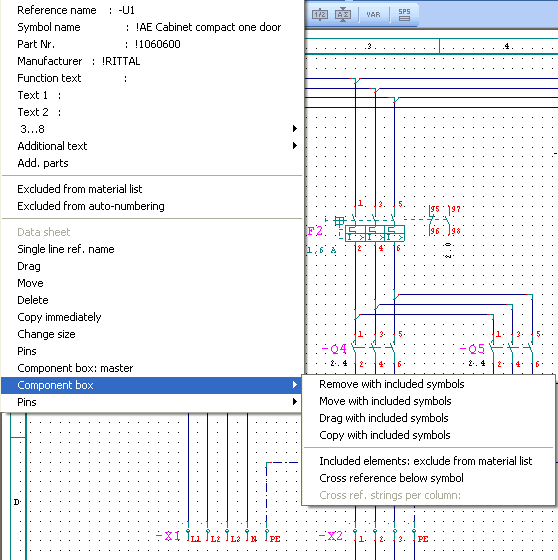
Please note that automatic management processes must be corrected depending on the parameter settings (symbol type).
Cross references
The component box can appear several times with identical reference names. The decisive symbol is then determined by a master assignment (in the symbol parameters). If for one reference the master was issued several times, the symbol which is recognized first by its coordinate is used for cross reference formation.
If you generate a cross reference course with the Automatic / Cross reference / Component box function, all found cross references are listed under the reference name of the master. If you want to have them positioned under the casing, set Cross reference below symbol in the parameter menu.
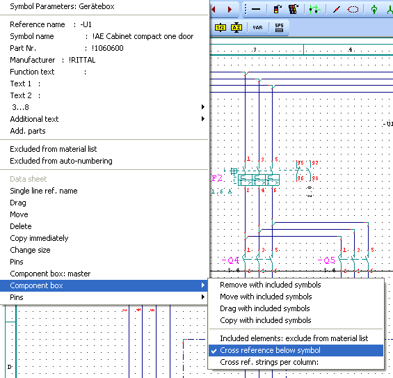
For many cross references, it is advisable to make a division into columns in the symbol parameter menu. This is possible only with the setting cross reference below, and the modifications are done via the input line.
Change size
You can subsequently change the size of the component box via the parameter menu. In order to do this, you click with the right mouse button on the symbol and select Change size in the parameter menu. You then have to select a corner of the casing and drag it to the correct size. The connections and the connection line are corrected automatically. If existing symbols are thereby included in the casing, they become part of the component box (the exceptions are contacts and additional elements).