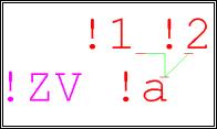
Normally the standard symbols supplied with the destination wiring library cover all applications. These symbols have been created in a 1.28mm grid and thus fit into the 2.5mm drawing grid which is normally used.
However, if you wish to create new destination wiring symbols, you must make sure that these T symbols (with 3 connection points) conform to the following rules:
Component type 'Destination wiring'
Reference name 'DW'
3 connection points
The common pin (which must only be connected to a component) is given the pin name '!a'
The pin which gives the 'primary' connection to the common pin, is given the pin name '!1'
The pin which gives the secondary connection to the common pin, is given the pin name '!2!
The component name should describe the intended application exactly
The grid spacing of the connection points must fit the drawing grid normally used
Rule
According to standard practice, the incoming connection line always joins pin !1 and the outgoing one leaves pin !2. The component to be connected is always attached to pin !a.
Example
Component name: T-piece down: Destination1 left -> Destination2 right
Component connection (Pin name !a)
Incoming connection from the left (Pin name !1)
Outgoing connection to the right (Pin name !2)
Reference name (!DW)
Tip
The shape and colour of the DW element should be drawn such that you can easily recognize both the common connection and the secondary connection.