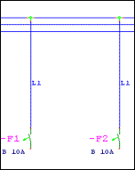
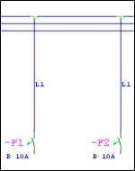
An advantage of destination wiring symbols is that automatic connection lines are established and also severed (horizontally and vertically) when DW elements are inserted. If you insert DW elements in a sensible manner and use automatic generation of the connection lines, you can largely do without the manual drawing of connection lines. Additional data such as connection name, section, length and color are not saved in the chart pages themselves, but in the ACCESS database. The name of this database is WSCAD - LTG in the appropriate project.
The database is updated by UNDO, REDO, Copy file, Delete file and the function Auto-conductor designations, but only within the project, i.e. when the file was not loaded as an external file (to the currently open project). When a project is started, an ACCESS database for the conductor designations is established if it does not already exist.
Attention
If the database is lost, it CANNOT be completely restored from the drawing files. Connection, color, section and length of the conductors will be missing in the restored version and will have to be added manually.
The data for color and section are not intended for representation on screen, but for edition in the list of connections. You can change the coloring on the screen under the menu item Settings / Colors for the connection lines and conductor designations. Please differentiate precisely between the destination wiring (for internal connections) and the cables (for external connections). In order to insert cables, you use cable management.
Important
If entire circuit chart pages are copied between projects or if you insert drawing macros, only the conductor designations are copied. The remaining data must be completed manually.
Angles serve to change the direction of the connection lines. Select an angle symbol from the DW.BIB with a click (left mouse button) on the symbol in the destination wiring bar, then after positioning (also with a click of the left mouse button), a link to the connections of symbols or other DW elements is created automatically. Be aware of the display (Tool tip) when you select the element.
The T-pieces create a connection between the connected devices and other DW elements. They make it possible to precisely trace the route of a line and serve for the branching of connection lines.
Line routing
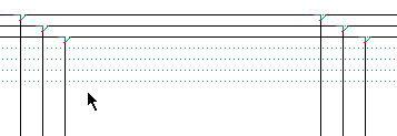
At the same time, T-pieces determine by their form the later course of the wiring (from a common connection to the primary target, from a common connection to the secondary target). As there are very many different forms of destination wiring elements in the destination wiring symbol bar, special attention must be given to the selection of the appropriate element.
Helpful is the fact that when you place three-core destination wiring elements (T-pieces) on a previously existing DW element or node, the previous one is deleted. In this way you can simply exchange DW elements!
A useful feature
As there are many different forms of destination wiring elements in the DW symbol bar, special attention must be paid to the selection of the appropriate element. A helpful feature is that when 3-pole DW elements (T pieces) are placed on an existing DW element or a node, the previous element is deleted. This allows DW elements to be exchanged very easily.
Rule
A common contact point, marked with a triangle, can ONLY be connected with a symbol, NOT with another three-core DW element.
Example of correctly used destination wiring

Analysis of the connection list for the correct application
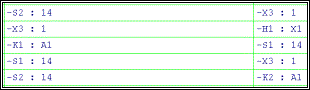
Example of incorrectly used destination wiring:
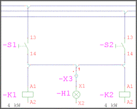
Error: The common connections of two DW elements (above K1 and K2) do not point towards the symbol connections.
Arrows serve to mark cable installations which have to end at one spot and then continue at another spot. For this you have to enter the line name and, if there are more than 2 line ends with the same line name, also the name of the connection. Other data, such as the color of the conductor, the section and length of this part of the line, are optional and taken into account only in the wiring chart.
If, for example, a connection line is generated automatically after the positioning of a DW element arrow, the line name dialog appears, where you can define the line name, connection, color, Cross section and length of the conductor that is to be installed:
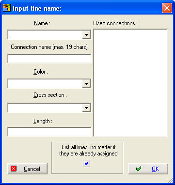
Enter a new line name and confirm with the enter key (not the OK button), or open the List field 'Name' and select an existing name. If connections with exactly the same line name already exist, these will be displayed in the large list field on the right.
Each open connection can only be assigned once (a beginning and an end each count as an open connection).
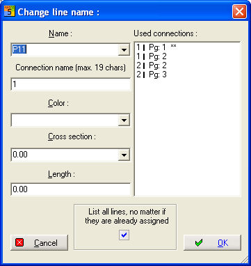
If you want to allocate a line that you have just drawn to a previously existing open line, select the corresponding entry in the list field on the right side with a double click. Previously existing data such as connection name, color, etc. are copied immediately. Otherwise, please give the line an additional connection name.
Only like this it will be possible to precisely identify this open line end later. After clicking the OK box, the line name will be automatically inserted and an Online line cross-reference can be generated. A new arrow symbol is on the cursor. Abort with <ESC> or with the right mouse button.
Note
The values for color and section are additionally saved in text files (Color.TXT or Section.TXT in the database directory) and are thus available for future input.
Example: In the drawing you can see on the right side the first arrow (direction right) with the line name L1, which you have assigned or entered as described above.
The next arrow is at the cursor and waiting to be placed (with a click of the left mouse button or by clicking <Return>).

When you place the element concerned >, lines are automatically extended to the left and connected with the nearest symbol connections or DW elements, provided that they are located on the same level.

You can issue an identical line name several times on one chart page (almost identical potential). Differentiation of the individual connections is ensured here by the information connection name. Individual connections can thus be precisely evaluated in a connection list.
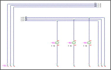
Example: Part of a possible application with line cross-references. The line cross-references point within the chart to the position where the respective connection continues.
You can considerably accelerate your working speed by using shortcuts instead of the usual selection of DW elements with the mouse.
Shortcuts DW elements:
|
Shortcut |
DW elements |
|
<Ctrl> - Arrow key left |
T-pieces left |
|
<Ctrl> - Arrow key right |
T-Pieces right |
|
<Ctrl> - Arrow key up |
T-Pieces top |
|
<Ctrl> - Arrow key down |
T-Pieces bottom |
|
<ALT> - Arrow key left |
Arrows |
|
<ALT> - Arrow key right |
Arrows |
|
<ALT> - Arrow key up |
Corner |
|
<ALT> - Arrow key down |
Corner |
After activating a shortcut, a small dialog appears which offers you the respective DW elements:
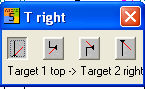
You can also navigate with the arrow keys. You make a selection with the enter key, and you can abort with the <ESC> key
If you create an open line in the traditional manner by manually drawing a connection line, the dialog for the connection parameter input appears just like when working with the arrow elements of the destination wiring:
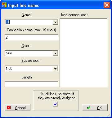
The new entry or assignment takes place in the same way as with the application of the DW elements.
But if you do not want to enter the information immediately when drawing the connection line or generally do without the input of the extended line information and only enter the line name, you can set this in the configuration:
Select Settings/Common Settings/Connect+Load :
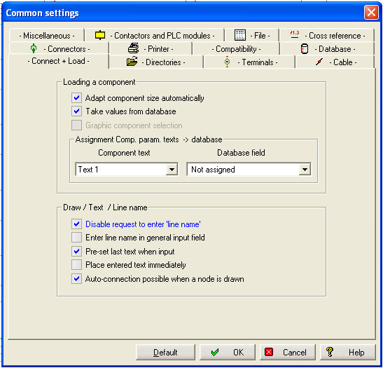
If the option Enter line name via general input field is activated, the dialog Enter line name does not appear. If you later enter or change the line name via the menu command Connecting + Loading – Line name, the dialog does not appear either.
The option Disable request to enter 'line name' avoids automatic activation of the input line or the dialog call when the drawing of a connection line is finished.
WSCAD 5 offers the possibility to also represent the three-core destination wiring element in point form.
You can switch the representation at any time with the menu command Schematic / DW point representation. Functionality is fully maintained.
|
DW point representation |
DW representation |
|
|
|
Note
Switching can only function properly if the correct destination wiring library is set in the configuration.