With UFD Area, it is also possible to draw a Unit and Field designation on an existing page which differs from the UFD on the page. I.e. the symbols within this area are located at another Unit and Field.
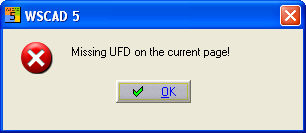
In a standard project (not a CPP project), identifications (UFD's) must be present in the drawing frame for which an additional independent UFD area is to be created. In other words, a Unit designation when the new area is to contain a system identification and/or a Field designation when the new area is to contain a location area. If this is not the case, a message will appear and the process will be aborted.
In a CPP project, systems are always present in the drawing frame and in most cases location identifications also. The symbol types to which the new area applies are coils, PLC main elements, standard symbols and terminals. Excluded are contacts, PLC auxiliary elements, cables, plugs and shields.
Caution
With terminals, you must specify new reference names for the terminal-strip component which lies outside the UFD area (i.e. when the terminal strip does not lie completely within the UFD area).

After activating the menu option, you must enclose the new UFD area with a rectangle.

After completion, a dialogue appears from which you can select a new Unit and Field designation. In a CPP project, you can select the system identifications from the existing part-projects, the location identification is according to choice. In a standard project, you can specify any system and location identification you like. During the input, the necessary characters = and + are produced automatically. The graphics can be organised using the parameter settings. The colour, type of line, text size and the text position of the UFD are changed.
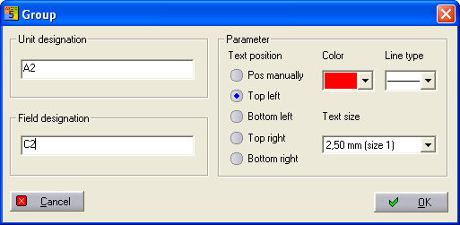
The UFD area is created and the Unit and Field designation (= H1+C1) is placed with OK.

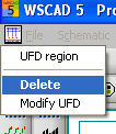
Once the UFD area has been created, this can be changed again later with a click of the right mouse button. In the context menu, the commands Delete or Change UFD are made visible. Delete removes this area again and corrects the display of contactor contacts and PLC auxiliary elements again (Contactor manager and PLC active). Change restarts the dialogue in which you can make changes (graphics and identifications) to the selected area.
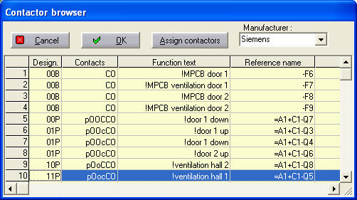
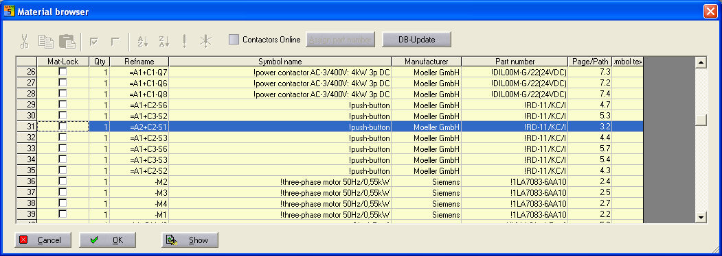
The use of the UFD area can be seen in the Material browser, for example. A new UFD is assigned to the emergency-stop key marked in the example. It is therefore recognised in all automatically generated lists.
For example, coil Q2 is given its own UFD area, and the contacts are copied in the reference name online.
Important: UFD areas can only be drawn, deleted or changed. No other operations such as copy or move, are possible, and neither is inserting a drawing macro into a UFD area.

Visible in the Contactor browser.