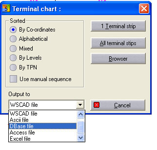
With the menu command Automatic funct. / Terminal chart, you open the Terminal chart dialog.
As output units in the compact and professional version, a terminal chart is entered in a WSCAD file (graphic form), a text file (ASCII) or a DBase- , Access- or an Excel file, either for one terminal strip or for all terminal strips. A terminal chart with an WSCAD file is standard with WSCAD 5 and already available in the compact version. WSCAD uses a graphic form, which you can draw up yourself very flexibly as a WSCAD drawing.
You define yourself, via so-called placeholders, which information you want to see in the terminal chart. This also includes, apart from terminal-related information such as destination specifications, line names, pin numbers, function texts and cable information (if cable conductors are not labelled, they are edited in the terminal chart with a predefinable *sign (e.g. x)), general information such as dates and file names. The exact listing of the available placeholders is available in the chapter form design. With the help of placeholders, the graphic form can very easily be adapted to your individual requirements.
* Input in configuration file necessary
WSPRJ5xAT.INI
[Config Terminal chart]
Default_KabAdr=x
Two destinations per terminal connection are managed on each connection side (internal / external). The destinations are the two closest connection points (seen from left to right; points that are located directly above the terminal connection have priority, though) of other symbols which are connected with the given terminal connection.
Sorting
According to coordinates: The terminals are edited according to their position in the circuit chart and always first from left to right and then from top to bottom.
Alphabetical: The terminals are sorted according to the terminal numbers. The sorting algorithm determines how terminal numbers consisting of digits and letters are to be treated.
Mixed: The terminals are first sorted according to the terminal numbers. Terminal connections which have only letters in the terminal name (e.g. PE) are placed between the terminals sorted by number according to the position in the schematic.
According to levels: The terminals are sorted according to their levels.
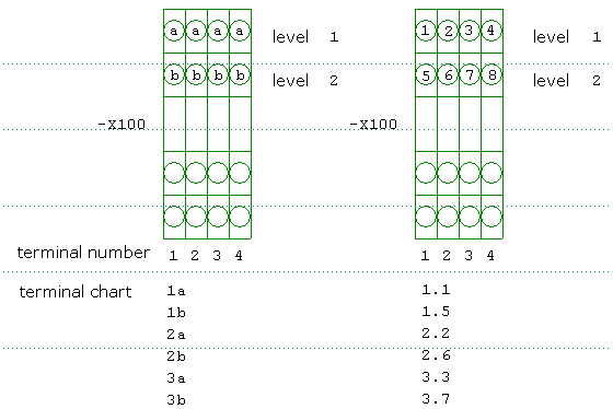
According to terminal position number (TPN): Sorting according to the terminal position number (TPN) results in the arrangement of multi-level terminal connections according to their position within the multi-level terminal.
Taking into account manual order: You can define any order for terminal edition in the terminal browser, which can be different from all other standard sortings.
Define the output unit: In the selection field Output unit, you can determine the destination of the output. However, the destinations Printer, WSCAD, ASCII, DBASE, ACCESS and EXCEL are available only in the professional version.
After activating the menu command of the output unit, you have to select the required box 1 terminal strip or all terminal strips in the dialog. In the File dialog, you now have to enter the file name of the new terminal chart and then select the desired terminal form on which the output is to be based. This is necessary in order to define the values which are supposed to be included in the output. External output options can be supplied with an automatic opening function.
Working as of WSCAD for Windows 4.3
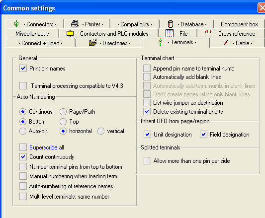
If you want to use the traditional terminal chart, you have to select the setting shown below.
Terminal chart compatible with V4.3