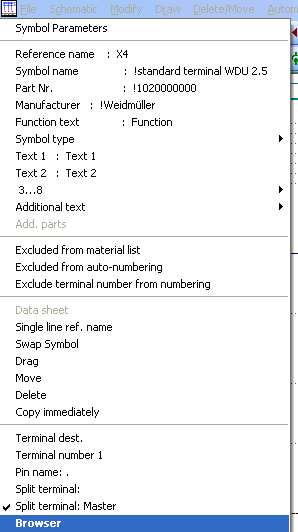
Distributed terminals serve to divide terminals in terms of representation. The WSCAD standard terminal consists of 3 connection pins. Thanks to the distributed terminal, these three connections can be represented individually. This also provides corresponding combination possibilities.
Condition
Only one terminal can be defined as master.
Representation in the browser
The terminal browser enables a summarized representation of the distributed terminals regardless of the position in the circuit charts. The distributed terminals are extended by a preceding + sign in the index field. If you click on this, you can see all the assigned elements of the terminal. All the field values of the browser can be displayed analogously to the standard terminals. Also, pin numbers and names can be processed. If you see a question mark, then there is a problem with the given terminal, for example, the master assignment is missing or there are too many elements; see terminal 4.
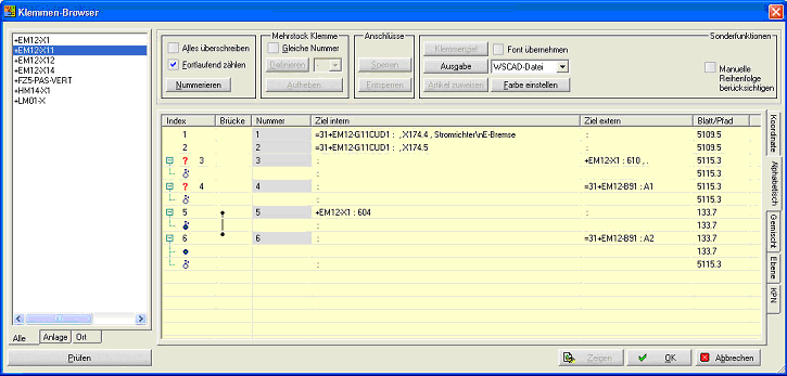
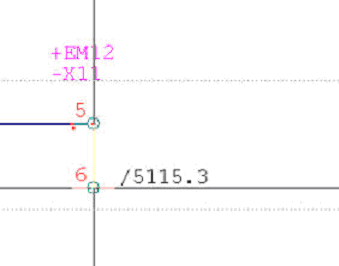
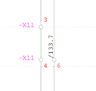
The terminal +EM12-X11 connection 6 was represented as a bridge pin on page 133.7 and used as an external destination on page 5115.3. The cross reference is generated by the cross reference run for the distributed terminals. The placeholder for the cross reference must be contained in the symbol.
Master assignment
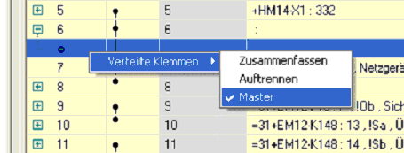
The master assignment can be modified by clicking with the right mouse button on the distributed terminal and by setting the Master option in the context menu. You can also recognize the master by its darker representation.
Summarizing
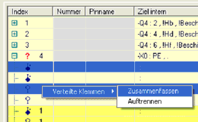
If you have positioned all terminals without assignment of numbers, you can carry out a summarization in the browser. To this effect, you select the associated terminals (Master + Slave) by multiple selection. Click with the right mouse button and select Distributed terminals / Summarize in the context menu. The summarized terminals then receive an identical index value.
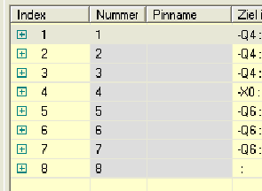
After restart of the browser, the distributed terminals will be listed individually.
Examples
Example 1
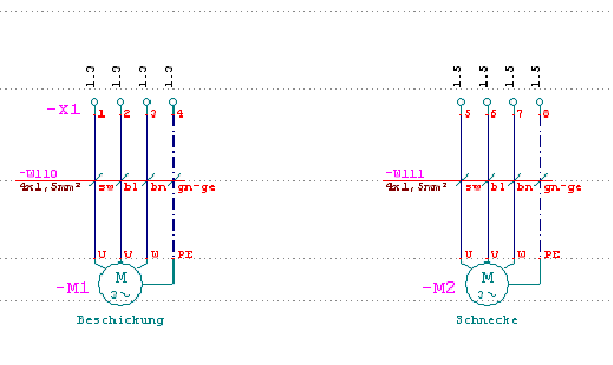
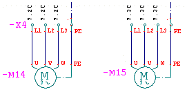
Distributed terminals are used here for motor feeders. The cross reference is generated with the Automatic / Cross reference run.
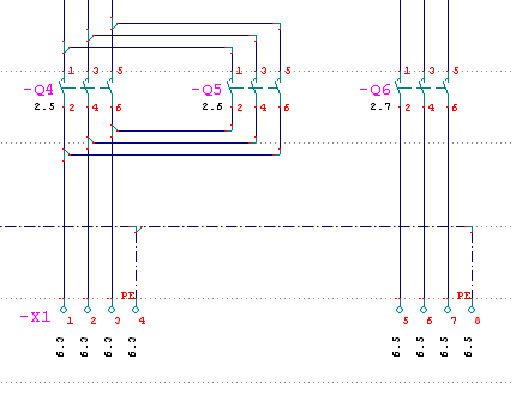
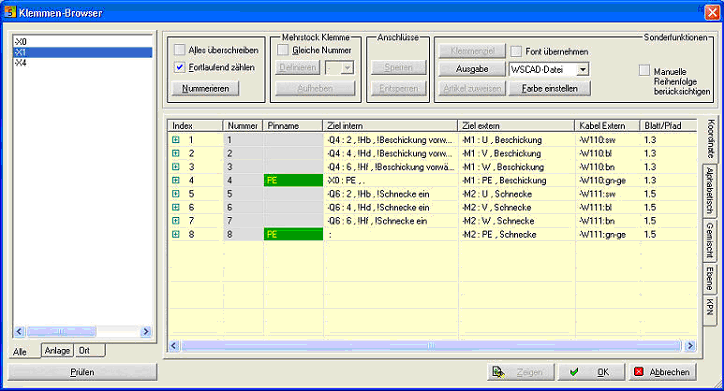
In the browser, you can see all the terminals with internal and external destinations.
Example 2
In the terminal browser, the terminal can be opened with a click on the + sign in the first column, and the element data is listed.
Picture is missing !!
Also, warning signs can be displayed in the first column:
T The parameters function text, text1 and text2 of the master element and the slave element/s do not correspond. In this case, automatic correction can be carried out with the button 'text correction' at the bottom of the dialog.
? The number of elements is not regular. Possible reasons are: there is no master element, there are several master elements, the corresponding slave element is not available, there are several slave elements. This does not necessarily mean an error! (See next example!)
The master element Internal destination is connected with several (now two) slave elements External destination. This means that two lines are connected to the external terminal destination (and these are represented in a different part of the drawing).
Drawing element 1 Drawing element 2+3
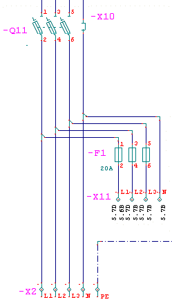
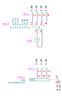
In this case, in the terminal browser:
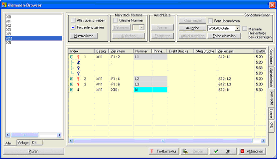
Of course there is a question mark in the first column next to the phase terminals, as according to the basic rule, there can be one internal destination, one bridge and one external destination. Now there are two external destinations. But the external destinations and the cross references are correct! Do not use more than two external destinations for the time being!
The automatically generated terminal chart (with the corresponding form) also shows the situation according to the circuit chart:
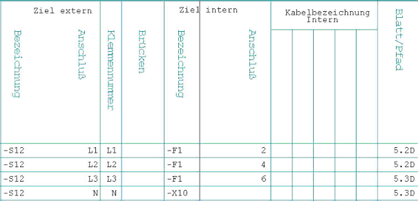
The terminal browser provides additional help for the management in practical cases. If there are several distributed terminal elements with identical codes (numbers, e.g. L1) in one terminal strip (same reference), it may be necessary to pair them manually.
Example:
Drawing element 1 Drawing element 2
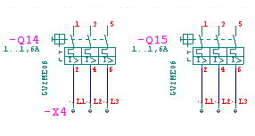
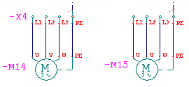
In the terminal browser, it is necessary to pair the individual pins:
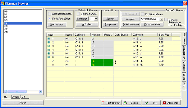
Mark the pins that belong together (<Ctrl> + left mouse button), then click with the right mouse button and select "Summarize" from the menu!
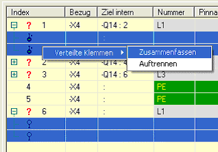
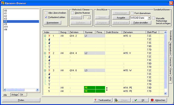
The command "Summarize" unites two or more marked elements under an identical distributed terminal ID.
The command "Undo" deletes the distributed terminal ID from two or more elements, so that new pairs can be generated.
The result:
Example (continued):
Drawing element 1 Drawing element 2
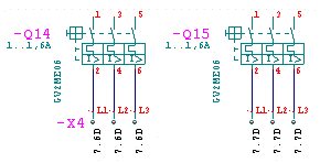
There must be two cross references !