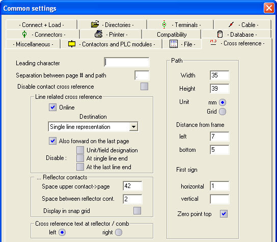
This tab covers all the settings for size, content, orientation and layout of cross-references displayed on the drawing.
Leading character
This character will become the first character of every cross-reference text. The default value is '/', but you also can enter a string.
Separation between page # and path
Here enter the sign, which is displayed in cross-reference texts between the page number and the path.
Disable contact cross-reference
With this option, you can prevent the generation of cross-reference text at contacts and (Mega module only) at side elements.
Also, forward on the last page
If a line has an open end on the right side and this line is not continued on the following pages, normally the cross-reference points at the line end itself. If you set this option, you can force the cross-reference text to point to a preceding page.
Disable Unit/field designation
If this option is NOT selected the UFD is included in the cross-reference text (at the beginning).
Disable at single line end
If a line has only one open end in the complete project, you can disable creation of the cross-reference text.
Disable at the last line end
Select this option if the cross-reference text at the last open end on the right should not be generated.
Space upper contact -> page edge
This option defines the location of the first reflector contact, and this is the reference point for the automatic positioning of the contact combs in the Professional module.
Space between reflector contacts
This option defines the space between the various contacts of a reflector (the duplicate contacts displayed next to the coil that are used to display the cross references).
Display in snap grid
If this option is selected, the contacts are placed 1 grid space away from the preceding contact. If disabled, the size of the contact is calculated and the distance away is adapted to this size. The previous setting 'Space between reflector contacts' then has no effect.
Cross reference text at reflector / comb
With this option, you can determine whether the cross-reference text at contact comb and contact reflector is generated at the left or right side.
Hint
The pin direction at the contact comb must be ‘left’ for the left-hand pins and ‘right’ for the right-hand pins. A wrong pin direction causes a missing cross-reference text!
Group path
With these settings, you can modify the path parameters. All entries can be made in mm or inches.
Hint
Be careful when setting the path unit to ‘Grid’. The cross references will change if the grid setting is altered.
The Distance from frame represents the space between your drawing frame and the format area. You can also set the start values (Blank = disable).
Hint
Remember that the path setting you can see in your drawing is only optical, which means there is no fixed relationship between what you see and the path settings used by the cross reference generator. You must therefore make sure the path setting matches the frame. You can easily check this by moving the cursor from left to right and noting the path information in the information bar.