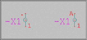
Drawing part 1
Drawing part 2
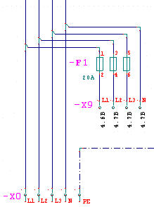
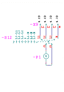
In particular cases, it may be necessary to reduce a terminal to its component parts and insert the individual parts in different places in the drawing so that they can continue to be administered as a unit by the automatic functions. In the circuit chart, the individual parts refer to each other with cross references.
Example:
|
Drawing part 1 |
Drawing part 2 |
|
|
|
Note:
Make use of this possibility only when it is absolutely necessary. Traditional representation of the terminals is clearer with regard to the interpretation of the drawing!
Special symbols should be created for the distributed terminals. In practice, this can be done according to the following logic:
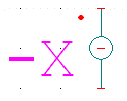 In case of traditional representation of terminals, the
symbol consists of three well defined elements (connection points).
In case of traditional representation of terminals, the
symbol consists of three well defined elements (connection points).
Internal connection (in the picture, the internal destination is indicated with a point)
Jumper connection
External connection
When creating split terminal symbols, it is possible to generate variants from one or two basic elements. Always set the correct symbol type! Use the symbol editor for this.
Procedure
Subsequent use of the terminal part symbols is very similar to the general WSCAD function "main element / additional element", but because of the differences, the designation "master element" is used here instead of "main element".
Manufacturer data is assigned only to the "master element" when it is inserted!
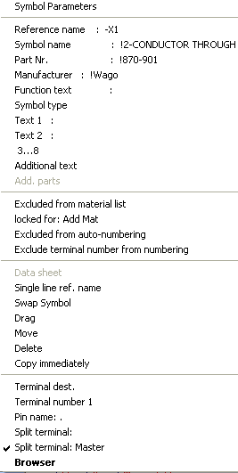
After loading the first terminal part (material data can be assigned), you click on it with the right mouse button and then select the line "Distr. terminal: master" in the parameter dialog. The latter will from then on be marked with a tick.
Important!
A terminal can have only one master element. The slave elements do not have to be marked. A terminal strip (same reference name) can contain several distributed terminals. The assignment of them is done automatically on the basis of the terminal number. In case of several identical terminal numbers (e.g. several L1), connection is established with the "distr. terminal ID". You receive further support in this respect in the terminal browser.
When further terminal parts are loaded, the references (in the example: -X9) and the terminal number (in the example: L1, L2, L3, N) determine the connection between the master and the slave element(s). Therefore, enter the terminal number after the selection! Check the correct pairings in the terminal browser! Modifications are also possible here!
Tip:
In the professional version, material data is assigned only to the master element! If you select further slave elements from the symbol explorer, press the <Ctrl> key during selection! The parts assignment process is not displayed!
When you have selected the split terminals, generate the cross references
in the menu 'Automatic funct.'!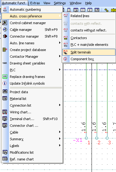
Cross references
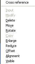
Should you wish to correct the direction or the position of the cross references, click the right mouse button while pressing the <Ctrl> key on the cross reference and carry out modifications with the context menu!
Split terminals are managed as a unit by the automatic functions. In the terminal browser, the elements can be separated, and further possibilities are at your disposal!
Note:
The function split terminals offers many other application possibilities! In view of further possibilities of development, we have not introduced any restrictions. Do not use this function for multi-level terminals!
Indication of which side of a terminal connection is internal and which is external is called the terminal destination. This simply means that connections assigned to the internal side have to have a defined pin name. In the case of libraries supplied by WSCAD, the pin name is predefined with " . ", but this can be any character (e.g. a, b or also +, -; see also: multi-level terminals). This point is visible in the circuit chart, but for printouts, this has to be explicitly released in the configuration.
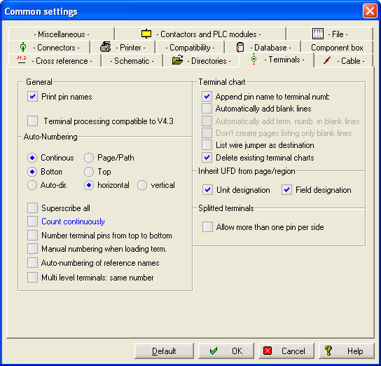
With the menu item Change / Terminal destination, the terminal destination can easily be turned round. The following illustration shows two possible representations of the terminal destination.