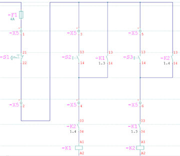
The following section explains how the automatic function creates the terminal chart. The automatic function finds the terminal pin position in the general connection file '*.CXK'. The destination reference is created as follows:
All component pins found on the same 'X' co-ordinate as the terminal pin are treated with highest priority.
If no connection was found on the same 'X' co-ordinate, the closest component pin to the left of the terminal pin will be selected, even if it is placed on a different drawing sheet.
If no connection was found to the left of the terminal pin, the closest component pin to the right will be selected, even if it is on a different drawing sheet.
The example on the following page shows a strange terminal chart, which the algorithm has created from a certain component arrangement. It is not incorrect, but is not practical.
-X2 pin 2 only locates the component K1/13 on the right side.
-X2 pin 3 sees X2 pin 2, marked for jumper connection, and on its left side component K1/13.
The external -X2 pin 5 in connected to K1 pin 13 on its left side and to K2 pin 13 on its right side. According to the algorithm, the terminal chart lists K1/13 again.
K1/13 is listed three times, K2/13 is not mentioned at all.
A practical solution, created with the Professional module, for the same arrangement is shown on page following the above example, but this time using terminals with 'jumper' pins.
Hint
The section on ‘Jumpers’ shows how, for the same drawing, the use of ‘jumper’ pins can create a more correct and more practical terminal chart in graphical form.