Horizontal comb
Vertical comb
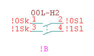
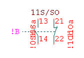
The symbol type must be a contact comb. The shape of the contact comb is unimportant for Automatic since a contact is logically identified with identical numbers in the case of pin names. Of course, the individual contacts should be drawn with a realistic shape.
|
Horizontal comb |
Vertical comb |
|
|
|
Pin orientation
|
Orientation |
Effect |
|
left |
for pins left of the horizontal comb |
|
right |
for pins right of the horizontal comb |
|
auto |
for a vertical comb |
With a vertical comb (in the case of circuit breakers), the pin direction should be determined automatically and then the pin names will appear vertical. The pin numbers however, can be entered horizontally if they are placed to the right of the pin. Automatic determination of the pin orientation is determined by the envelope of the symbol. A pin at the top right corner is placed on the right automatically.
Example: If the cross reference on a vertical comb does not have the desired orientation (e.g. because the contact is on the right of a normally-open contactor so that the pin is automatically placed on the right), then this can be put right by moving the line of the normally-open contact to the right by 1 pixel (not 1 snap). The pin therefore no longer sits precisely on the corner but on the upper edge of the envelope.
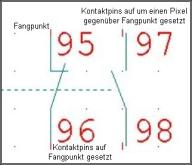
Pin name
The pin name of each contact determines the contact type. Each pin must have one pin name and identical pin names of course for each contact. By doing so, the individual contacts of the comb can be easily assigned.
The pin name is structured as follows:
The pin name begins with a ! character (so that it is invisible on the plan) which is followed by a number (0-9) as a serial contact number. The first contact must start with 0 and the next with 1-9. The following types are supported.
Note
All the connections of a contact must have a unique number.
Pin numbers
The pin numbers of the individual contacts of the comb are used as a reference for loading and assigning the contacts. When loading a contact, this is pre-assigned with the pin number of a free contact from the comb. The pin numbers may consist of up to any 6 characters but they must be numbers.
Reference name
The reference name of the comb should be present but only the position is required since, after automatic loading, the comb is given the same reference name as the coil prefixed with the !.
Insertion point
The insertion point of the comb is important as a reference point for the automatic placement of the comb when no comb has yet been assigned to the coil. With combs which have been placed beneath the coil (standard contactors), the insertion point should be placed precisely on the centre of the upper contact. With combs which are positioned to the side (e.g. circuit breakers) the insertion point should be placed correspondingly lower and as far to the left as possible.