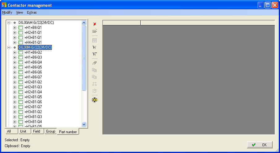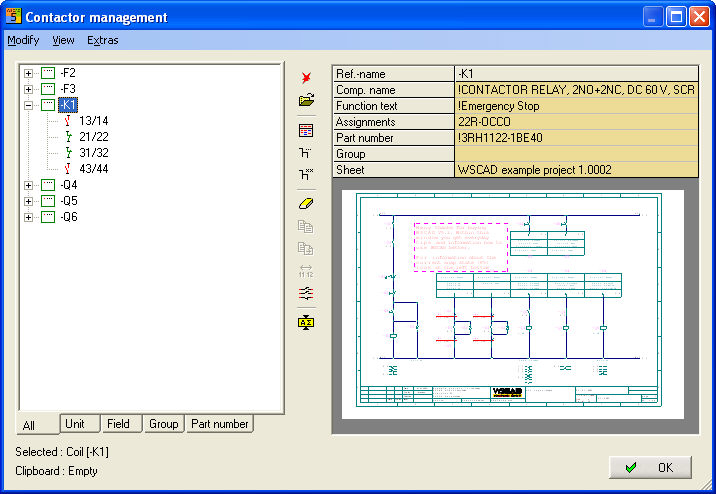
Editing in the Contactor Manager is similar to editing in the Project Manager. All information is taken directly from the contactor database.
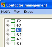
The existing reference names (of the contactor coils) appear in the Contactor Manager on the left. Each entry corresponds to a coil (or even a virtual coil).
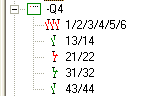
The contacts can be seen inside the coil, where the red marking indicates that the contact is being used.
Here, the graphics presentation shows the status of the coil.
|
Symbol |
Description |
Explanation |
|
|
Green box |
Coil has item number with defined number of contacts and is already positioned on the page |
|
|
Green box with red cross |
Coil is available on the page. Item number and contact are not yet determined or not positioned |
|
|
Grey box with few points |
Contact is already positioned on the page but coils are not yet available on the page (virtual contactor) |
|
|
Grey box |
Reference name of the coil is being managed but neither contact nor coil are positioned on a page on the circuit diagram |
|
|
Grey box with points filled |
Virtual contactor: Coil not yet available on the page but the comb is fully assigned |
|
|
Green box filled red |
Various fields during the coil-to-contact-to-contact-comb assignment |
|
|
Green box with points filled |
Coils fully assigned. Addition of boxes due to expansion of the contact comb |
|
|
Green contacts |
Contact free |
|
|
Red contacts |
Contact assigned |
|
|
Box red with contacts |
Comb not available, item missing |
Located on the right in the Contactor Manager is a table which is used for the display and entry. The display depends on the element selected on the left side. There are two possible views: the coil (click on reference name) or the contact. You will then see the information and the preview of the file where the selected element occurs.
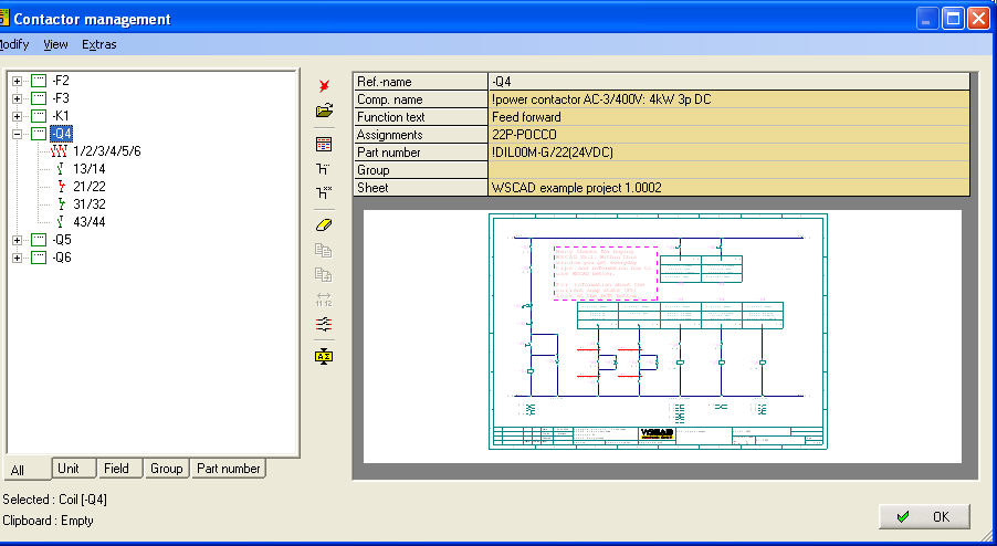
When you click on a coil
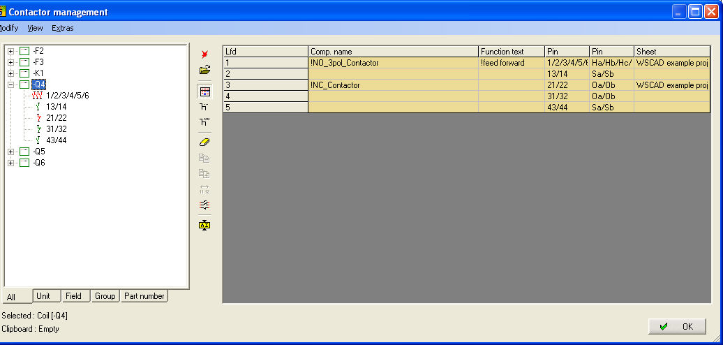
Again, there are two views: List
or Standard. Either of these can be selected via the menu View
/ List or the command-bar button.

Standard view
Standard view shows all of the information about the component name, function text, assignment, item, group, page ….. as well as a plan preview of where the element is located.
|
Field designation |
Function |
|
Component name |
Contents cannot be edited either from the symbol name or from the database |
|
Function text |
This is where the function text for the coils is shown. This can be changed or entered again. (! makes the text invisible) |
|
Assignments |
This is where you will see the designation of the contact comb which cannot be edited |
|
Part number |
This is where the part number is shown and can be changed by a double click and invoking the database. |
|
Group |
This is where the functional groups can be entered to make it easier to sort the coils in the Contactor Manager. |
|
Sheet |
Shows the number of the page on which coil is positioned |
List mode
List mode shows all the connections to component name, function text, connection, pin and page.
|
Field designation |
Function |
|
Component name |
Contents either from the symbol name or from the item designation (cannot be edited) |
|
Function text |
This is where the function text for the coil is shown. This can be changed or entered again. (! makes the text invisible) |
|
Connection |
This is where you will now see the pin numbers for individual connections (can be edited) |
|
Pin |
This is where the internal abbreviations of the connection pins are shown. These determine the contact type (cannot be edited) |
|
Page |
Shows the number of the page on which coil is positioned (cannot be edited) |
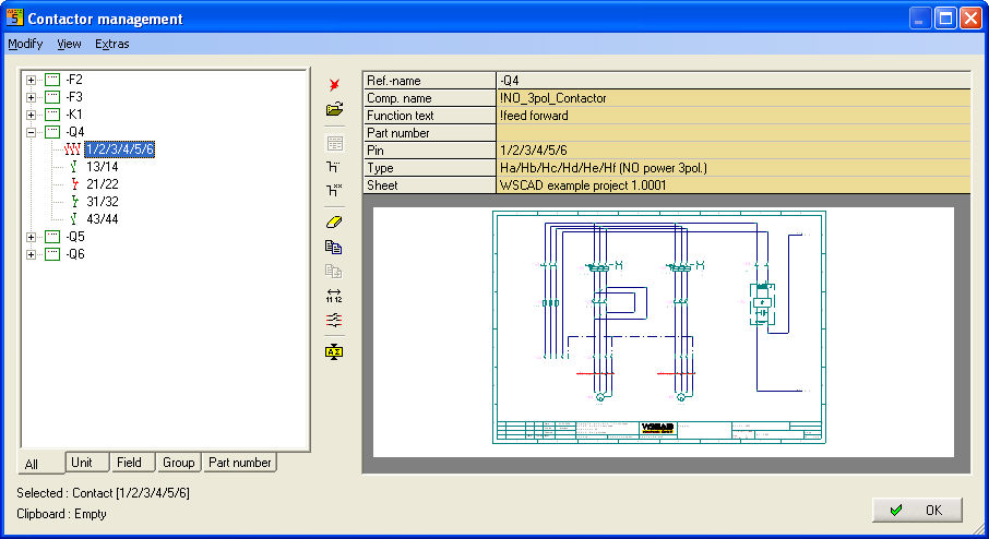
When you click on a contact
Here, there is only one view standard.
|
Field designation |
Function |
|
Component name |
Contents of symbol name (cannot be edited) |
|
Function text |
This is where the function text is shown. This can be changed or entered again, even if a contact has not been used yet. (! makes the text invisible) |
|
Part number |
|
|
Pin |
This is where you will now see the pin numbers of individual connection (can be edited) |
|
Type |
This is where the internal abbreviations of the connection pins are shown. These determine the contact type (cannot be edited) |
|
Page |
Shows the number of the page on which coil is positioned (cannot be edited) |
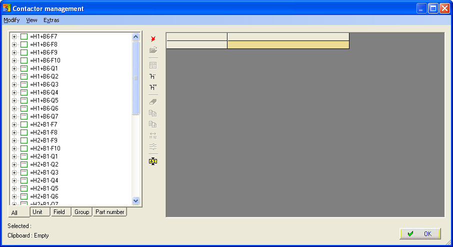
The display in the Contactor Manager can be structured using the tabs.
All
The tab All shows all the reference names listed in alphabetical order.
Unit
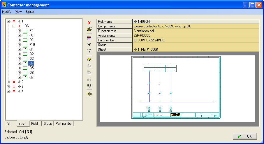
The tab Unit shows a structure according to designation in a CPP project
Field
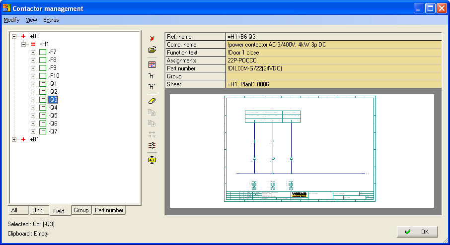
The tab Field shows a structure according to UFD in a CPP project.
Group
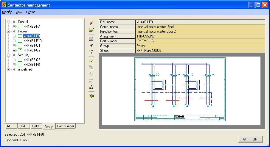
The tab Group supplies a structure according to any function groups which can be defined for each reference name (contactor coil) in the field Group.
Part number
The tab Part number supplies a structure according to item numbers which can be created for each reference name (contactor coil) in the field Part number.