Side (additional) elements
Case A;
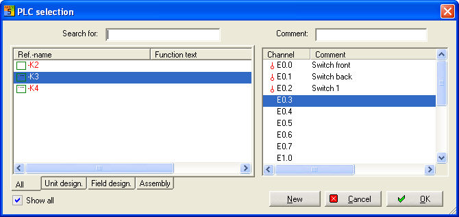
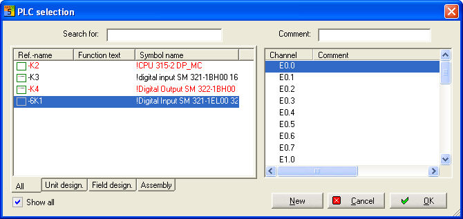
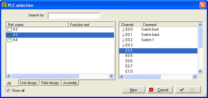
If you wish to insert PLC additional elements into a project, you first have to place the PLC additional element (PLC input and output represented separately). PLC main elements already contained in the project will then be listed in the PLC selection. In the dialog, you will see all the main elements (sorted according to the tabs All, Unit design., Field design., Assembly) on the left and all the inputs and outputs of the respective main element on the right.
At the top left, you will see an input field for a search term. The term will be searched for in the reference names of the given main elements (input, e.g. =H3).
At the top right, you will see an input field for a commentary text, in which you can immediately enter the commentary text for the respective input or output.
Also take into account the option Show all, which shows fully assigned PLC-main elements or those which do not have the right connection type.
The view Assembly group offers a selection of the currently used assembly groups.
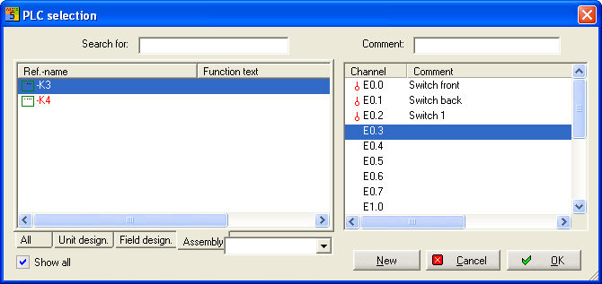
Select the main element here and then the corresponding connection. Immediately enter the commentary text as well. In order to see which PLC main elements are already fully assigned, they will be marked in red in the PLC selection. They will also be marked in red if no valid connection is free.
Case B;
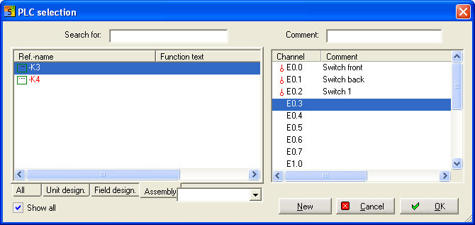
Insert a new PLC additional element in the circuit chart in order to start PLC selection.
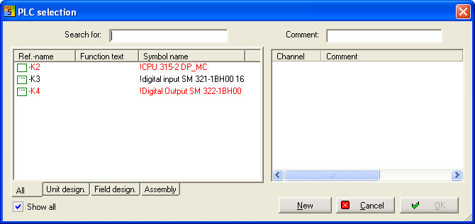
Select New, then enter the reference name or take the offered.
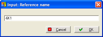
After OK, parts management opens where, depending on the symbol, the possible entries will be displayed.
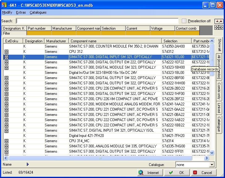
Select library if there is no allocation to the symbol !
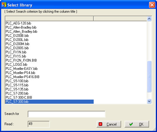
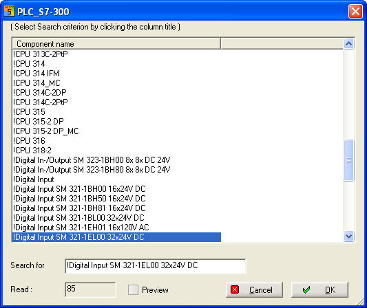
Search for the right entry. PLC selection will then be displayed with the new reference. Select input or output and confirm with OK .
 V
V
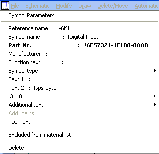
Info about Symbol Parameters
Note
If you use multi-digit pin numbers in the main element, e.g. EAZ, exactly the same pin name must be used in the additional element, because otherwise the PLC manager will not see any correspondence, and you will not receive any free channels in the PLC selection dialog. This can be remedied with a rather unusual entry in the WSWIN5xAT.INI file, which is as follows:
[Config Contactor/PLC]
PLC_EXACTCHECK=0
With this switch, any check of the connection is switched off:
PLC_EXACTCHECK=-1
Note
If you copy an side element via Process-Copy or Copy now, an existing commentary will be copied.
Main elements
Case A;
Insert a new PLC main element in the circuit chart in order to start PLC selection.
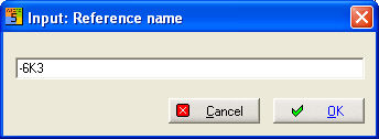
Select New, then enter the reference name.
After OK, parts management opens where, depending on the symbol, the possible entries will be displayed.
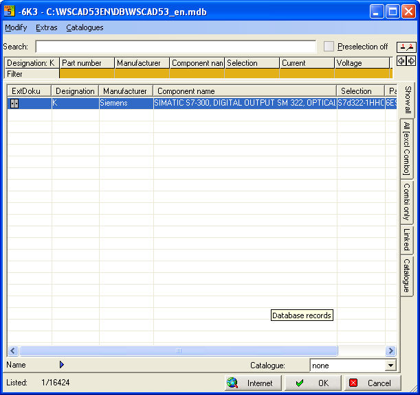
Search for the right entry. PLC selection will then be displayed with the new reference.
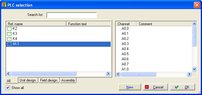
Finish with OK. The parameter dialog then starts in order to complete the data.
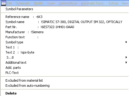
Case B;
If you want to insert PLC main elements in an existing project but which is already virtually in the circuit chart (e.g. An additional element was placed earlier), then the PLC main elements already contained in the project will be listed in an overview after placing the new PLC main element. In this case, select the virtual module (light-grey symbol).
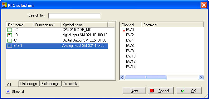
Confirm with OK. The virtual element will then be copied.
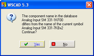
Should a discrepancy be discovered between PLC database information and the symbol name, you can either accept or reject this discrepancy. In this case, another part has to be selected via parts management.
Note
In the case of the PLC main element, the part can be changed via the symbol parameters. You receive information that no replacement of construction elements in the chart pages is carried out as only the part number is changed.