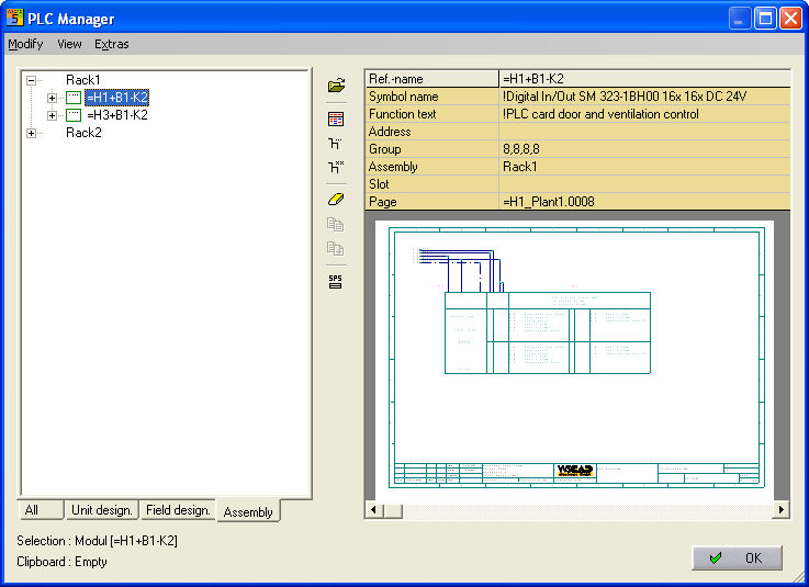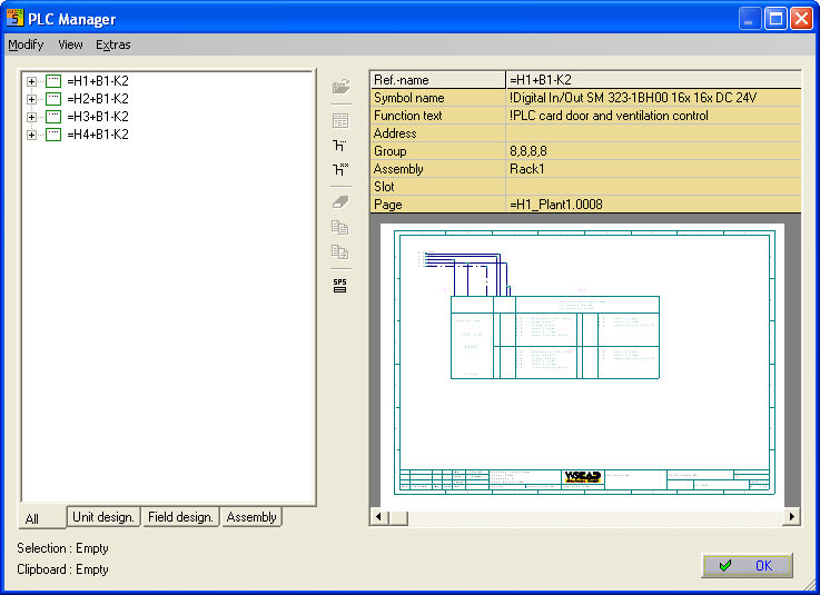
Editing in the PLC Manager is similar to editing in the Conductor Manager. All information is taken directly from the PLC database.
Left side
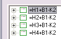
The existing reference names are shown on the left in the PLC Manager. Each entry corresponds to a main element.
The picture shows the status of the main element.
 Few
points in the picture corresponds to a main element which
is not fully assigned.
Few
points in the picture corresponds to a main element which
is not fully assigned.
 Many
points in the picture corresponds to a main element which
is fully assigned.
Many
points in the picture corresponds to a main element which
is fully assigned.
 Grey
graphics corresponds to a virtual main element which is not
fully assigned (i.e. the main element has not been placed on
the circuit diagram).
Grey
graphics corresponds to a virtual main element which is not
fully assigned (i.e. the main element has not been placed on
the circuit diagram).
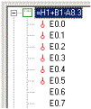
The connections can be seen within the main element itself. Here, the red marking means a connection which has been assigned or an side element which has been placed.
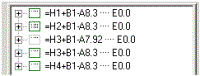
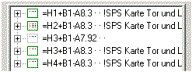
The function
texts and the start
addresses can be displayed. The menu command
View/Start addresse and View / Function text are available
for this purpose or use the middle command bar commands Start addresses
 and Function text

Right side
A table which is used for the display and entry is located on the right in the PLC Manager. The display is dependent on the element selected on the right side. There are two possible views. The main element (click on the reference name) or the side element (click on the connection). The side element also shows the preview of the file, where it exists, in addition to the connection information.
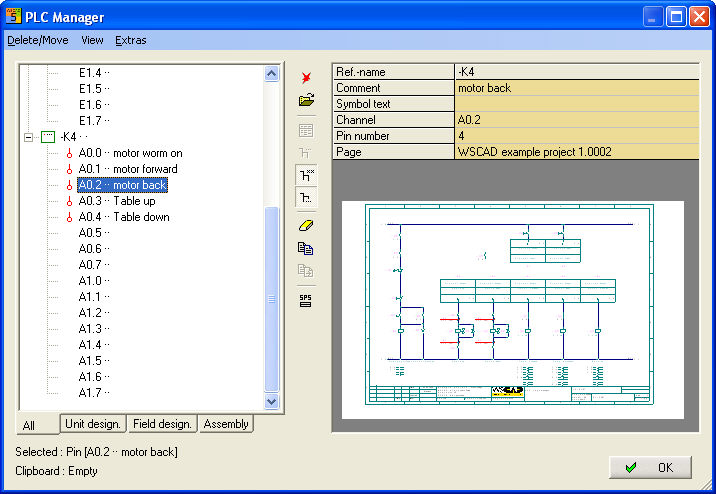
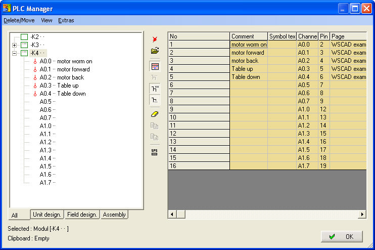
Again, with the main element, there are two
views: List or Detail, which can be toggled via the menu
View / List ( ) .
) .
List mode shows all of the connections with Comment, Symbol text, Channel, Pin numbers and Page.
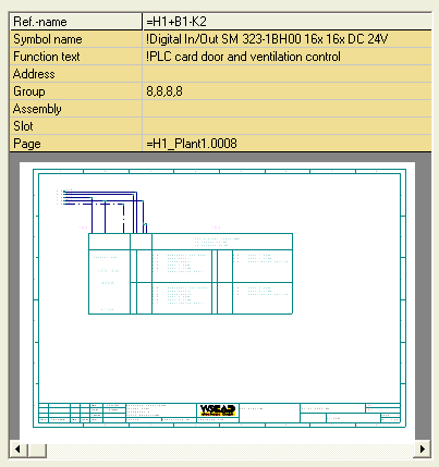
Detail mode shows all of the information about the Symbol name, Function text, Address e.t.c. as well as a plan preview of where the element is located.
Tabs in the PLC Manager
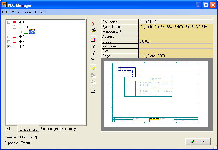
The display in the PLC Manager can be structured using the tabs.
The tab All shows all the main elements (reference names) listed in alphabetical order.
The tab Unit design card shows a structure according to Unit identification.
The tab Field design card shows a structure according to Field identification.
The tab Assembly design card shows a structure according to Assembly identification.
Example Unit design:
Example Assembly: